Parallel instruction
For reasons that I will explain later, it so happened that almost immediately after the assembly of the ARL 44, the American heavy tank T29E1 from HobbyBoss was also assembled. The tank, by the way, is also extremely brutal looking. Similarly to the previous model, I see no reason to post a review of the box or the progress of my assembly, but I bring to your attention again a parallel instruction, i.e. concentrate of impressions from the assembly, fixed with a fresh mind.
With the French tank, I was glad that its rollers were small, and the tracks were large and there were few of them. Here God took revenge on me. If the rollers are normal: there are 18 main and 7 supporting ones, all doubled. All are given with a margin.
But there are 240 tracks, of which 226 will be used. There is a reserve, but it is small, and they are fragile. Each track has 3 feeders. Plus there are two more connectors, one on each side, and they are different. They are given with an even larger margin (248 each), but very small.
I must say that the eminence and experience of the manufacturer affects. If Amusing Hobby has a dime a dozen jambs in the instructions, then HobbyBoss has an order of magnitude less.
So, let’s begin:
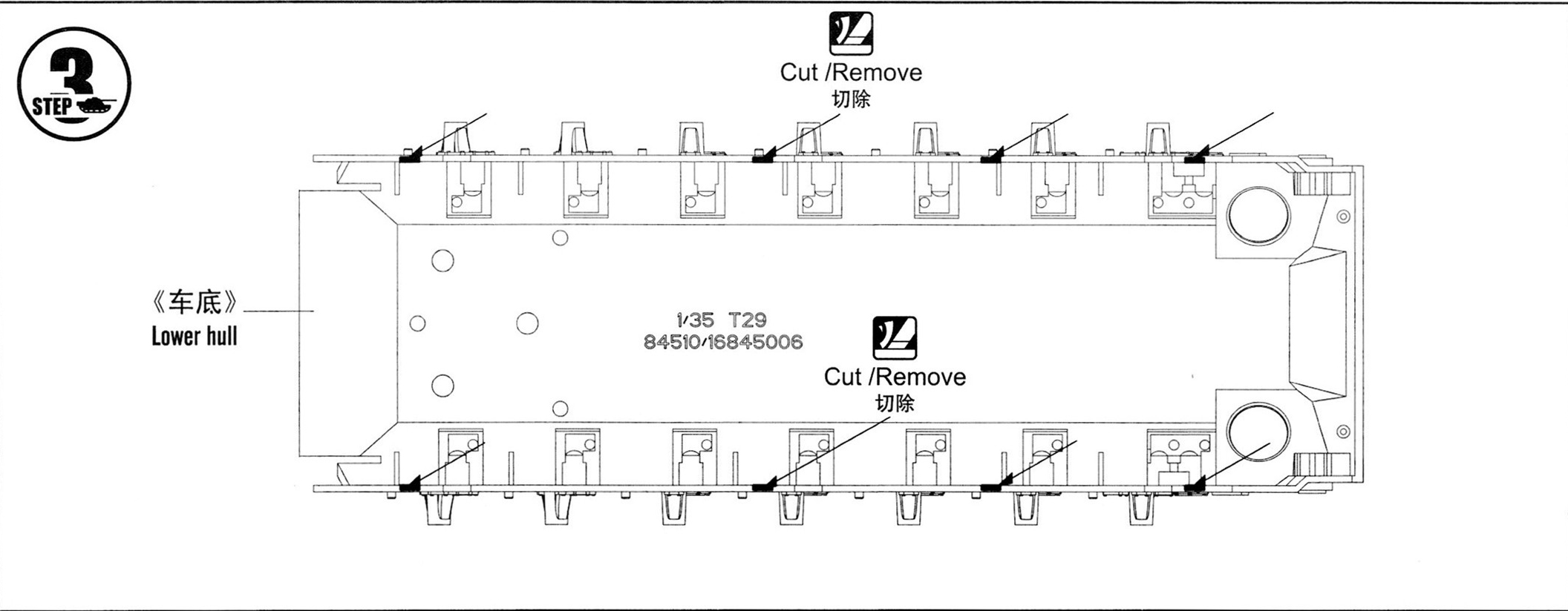
- At step 3 of the instructions, I would recommend trying on the top and bottom of the case in order to clearly understand what really needs to be cut off and why. There is a risk of cutting off the necessary guides.
- When assembling the undercarriage, one must be extremely careful and realize that in the instructions the hull bath is given upside down. For example, I’m used to keeping parts in the correct orientation.
- The second model in a row in which the headlight lenses are given by opaque parts. One recalls a bearded army joke: “Clog a window with plywood and paint it with transparent paint.“
4. In parts B3 drilled 0.8mm mounting holes for part B12.
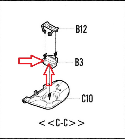
Maybe not necessary, but it’s better.
- When gluing parts B27, and there are already 4 of them, the main thing is not to make a mistake with the direction of the comb.

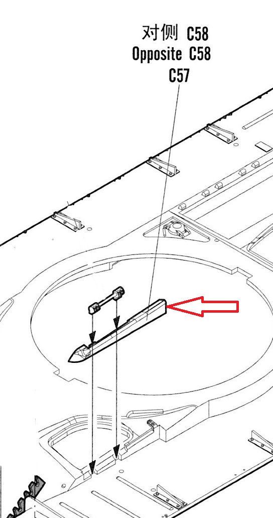
- When gluing part C57 (C58) you don’t have to worry about the back gap, it will then close at step 10.
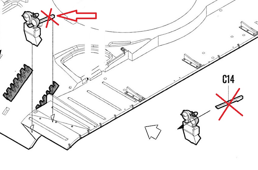
- I did not glue the C14 part – it looks too clumsy and foreign.
- The instructions do not indicate the sequence of gluing the overhead grilles. I started with the front ones. I bit off both, processed and it became not clear which of them was which part – they are completely interchangeable, the difference is only in the tilt of the blinds on the grilles.
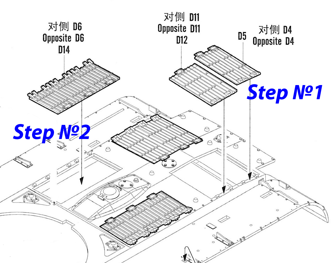
But the pairs of parts D4 + D11 (by the way, there is a typo) and D5 + D12 are not interchangeable and can only be glued correctly (with the correct orientation of the sides with loops and handles). Having glued them correctly on them, decide on the slope of the blinds and at the front grids.
I have them oriented in different directions, but the front grids are almost completely hidden under the tower, so it’s not particularly visible.
Although making the grilles a solid plastic part is a bad form.
- In steps 8 and 9, it’s time to get serious about how you’ll be making the many staples – detail A7.
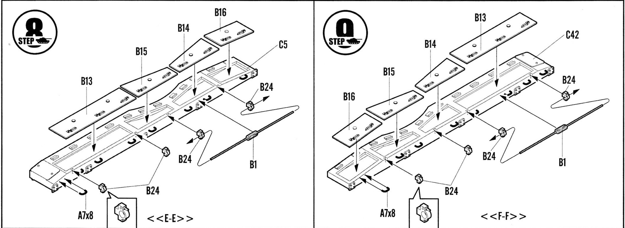
Look at the frames – how small and thin these staples are, i.e. fragile and easily lost. And you need a lot of them: there are 7 pieces on the boxes on each side, 12 more pieces on each fender, for a total of 7 * 2 + 12 * 2 = 38 pieces. And there are 48 of them on the sprues, i.e. There is a supply, but not that big.
I will add to this that the places of their installation are marked very faded.
If you do not have wire cutters, similar to these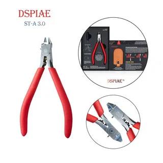
it is better to immediately take the wire and bend them yourself. And drill out the attachment points.
- In the same place: there is no need to first insert the B11 part into the B24 parts and then glue it, as the instructions recommend. B24 parts have such huge holes that B11 can be inserted after gluing. You can check on a free pair of these parts.
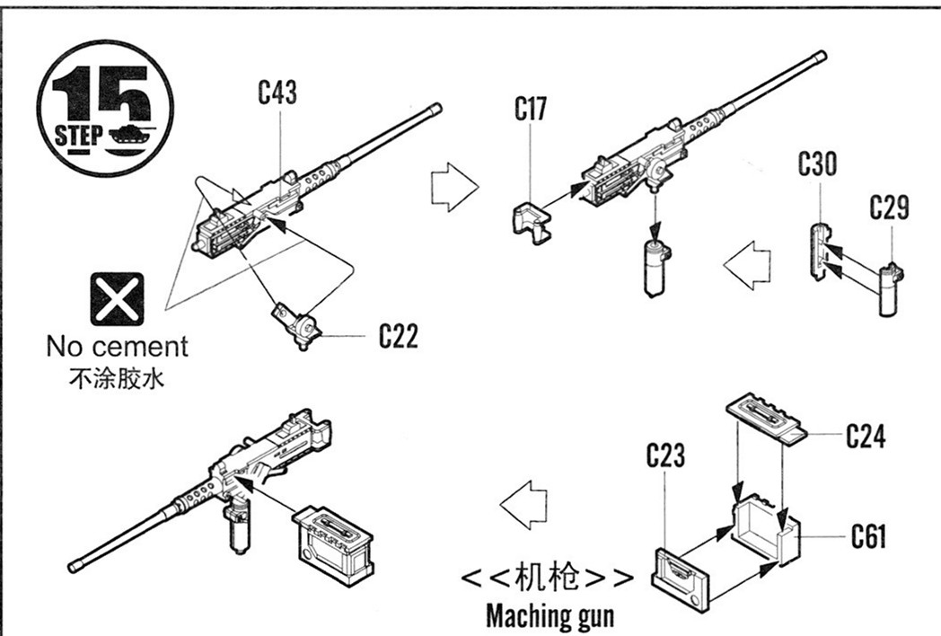
- In step 10, I reamed the barrel of the machine gun and a little muffler outlet. But this is my personal initiative.
- It took me more time to implement step 11, assembling the tracks, than the rest of the tank.
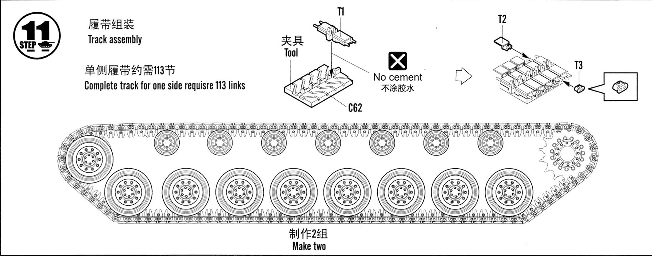
Locks T2 and T3 refused to stay on the pins of the track and flew off at the slightest movement. As a result, everything fell apart. I had to flatten these pins a little and only then connect them. And they are thin and fragile! If you squeeze too hard – they will not fit into the holes, if you squeeze it too little – they will fly off.
It is also important that the sections belonging to different tracks must be mirrored. Having installed the next 5 tracks in the conductor, I looked very carefully at which side to insert which connector. And still, I was wrong once.
- The turret of the T29 tank has a very rough molding texture (By the way, advise a good photo tour of the tank. I didn’t find it. I don’t really like the video.)
 just like Soviet tanks during the WWII.
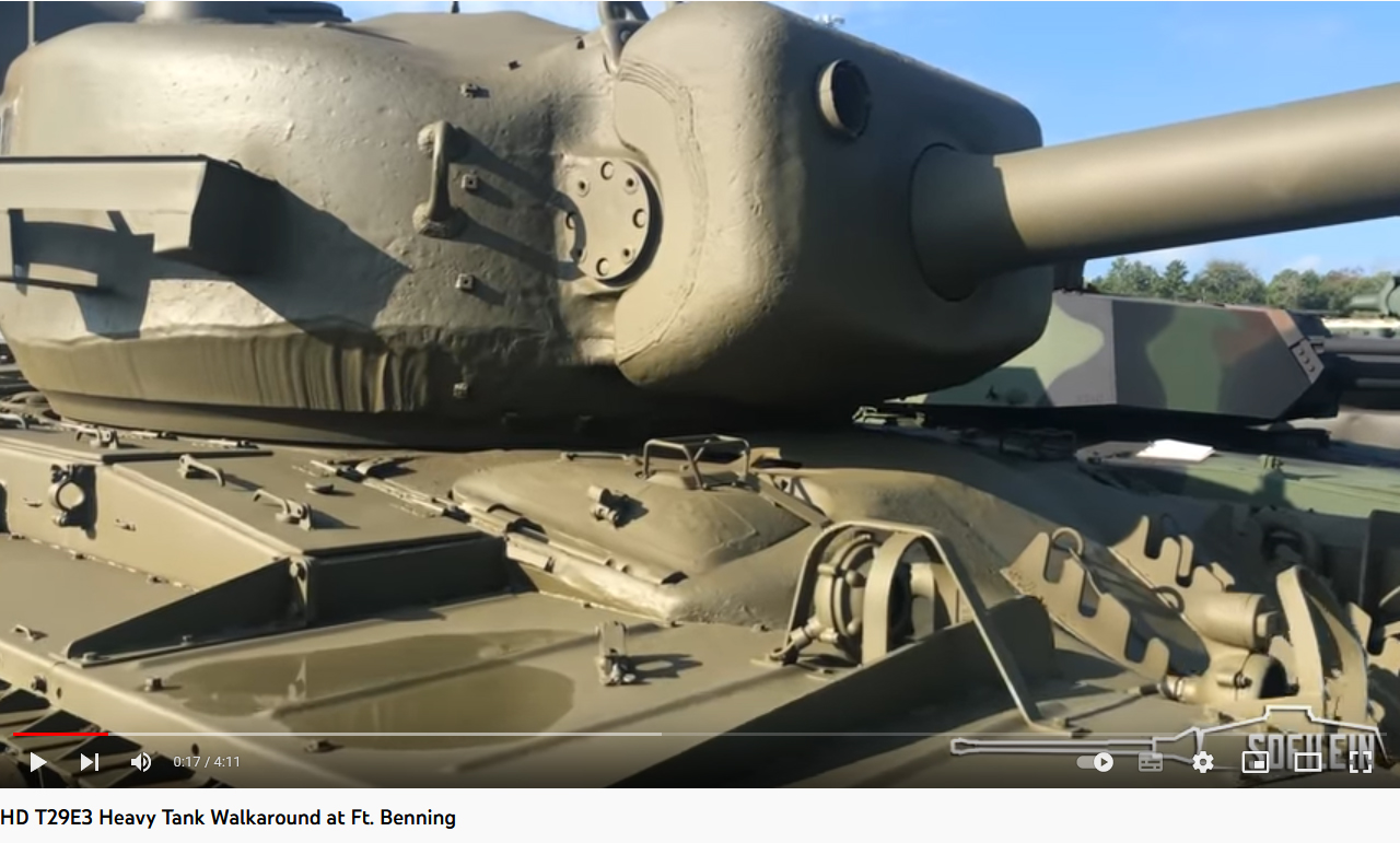
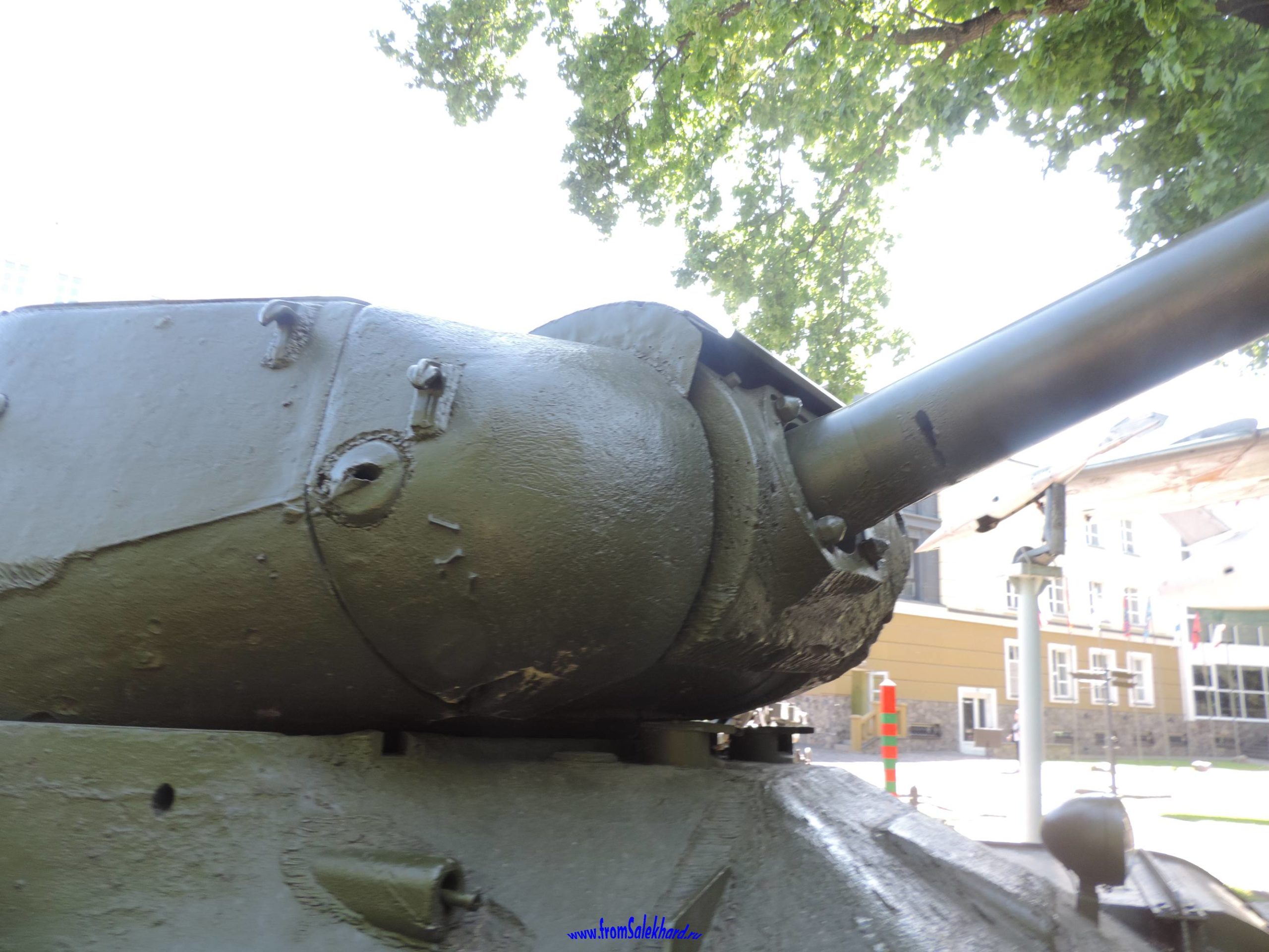
And the top of the tank turret matches this perfectly.
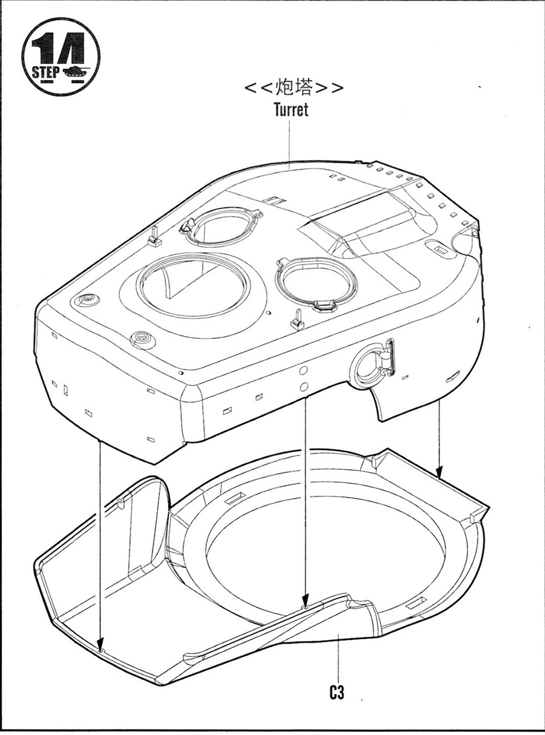
But part C3 is smooth! So, squirm as you like!
- I also drilled the barrel of an anti-aircraft machine gun – a habit.
- I was not able to assemble the knot in step 16 in such a way as to maintain mobility.

Then I had to carefully break it down and simply insert the C9 part into the C4. They fit snugly enough into each other and now hold without gluing.
- Also, according to tradition, I first glued the mask of the gun, and only then began to glue all the small things on the turret.
- My heart sank as I looked at the opaque windows of the commander’s cupola.

I even wanted to choose with a drill, but then changed my mind, afraid of the difficulties and the risk of damage.